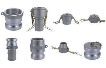
When selecting or replacing a Camlock coupling, nominal size is only the beginning. For standard applications, a 2-inch Camlock may be identified simply as a “2-inch coupling.” However, engineers, maintenance teams, and OEM buyers often need more detailed information to ensure that the fitting will physically and functionally fit their system.
Understanding Camlock coupling dimensions is particularly important when replacing an existing fitting, designing a hose assembly, checking equipment compatibility, or specifying custom components.
This guide explains the most important Camlock fitting dimensions, what they mean, and how to use dimensional drawings when selecting a Camlock coupling.
Why Camlock Coupling Dimensions Matter
Two Camlock fittings may have the same nominal size but different overall dimensions depending on:
- Fitting type
- Connection configuration
- Material
- Thread standard
- Hose shank design
- Manufacturer
- Applicable standard
- Special or customized construction
For example, two 2-inch Camlock fittings may both connect to a 2-inch system while having different overall lengths or threaded configurations.
Therefore, nominal size alone should not be used as the only dimensional specification for an OEM or replacement application.
Nominal Size vs. Actual Dimensions
The nominal size of a Camlock fitting describes its standard connection size.
Common sizes include:
- 1/2 inch
- 3/4 inch
- 1 inch
- 1-1/4 inch
- 1-1/2 inch
- 2 inch
- 3 inch
- 4 inch
- 5 inch
- 6 inch
However, the nominal size does not necessarily represent every physical dimension of the fitting.
A 2-inch Camlock may have:
- A 2-inch nominal connection
- A larger outside body diameter
- A different thread diameter
- A different hose-shank outside diameter
- A specific overall length
This distinction is important when space is limited.
The Most Important Camlock Dimensions
When reviewing a Camlock coupling drawing, several measurements may be important.
1. Overall Length
Overall length is the distance from one end of the fitting to the other.
This measurement is particularly important when the fitting is installed:
- Inside machinery
- Near a pump
- Inside a cabinet
- On a tank
- In a compact piping system
- In an existing hose assembly
A replacement fitting with the correct nominal size but a significantly different overall length may interfere with nearby components.
2. Body Diameter
The outside diameter of the Camlock body affects the physical clearance around the coupling.
This is especially important where several fittings are installed close together.
Body diameter can vary depending on:
- Material
- Size
- Manufacturing design
- Coupling type
Always use the manufacturer’s dimensional drawing for precise clearance requirements.
3. Thread Dimensions
Threaded Camlock fittings may use different thread standards.
Common specifications include:
- NPT
- BSP
- BSPT
- JIS
- Other customer-specific thread configurations
Important thread information may include:
- Thread type
- Nominal thread size
- Major diameter
- Thread pitch
- Number of threads per inch
- Thread length
Never determine thread compatibility from diameter alone.
A fitting can have a similar-looking thread but still be incompatible.
NPT vs. BSP: Why Thread Dimensions Matter
One of the most common mistakes when ordering threaded Camlock fittings is assuming that similar nominal sizes automatically mean interchangeable threads.
For example, NPT and BSP thread systems use different thread geometries.
Before ordering a threaded Camlock fitting, confirm:
- Thread standard
- Nominal size
- Male or female thread
- Required thread length
- Equipment connection specification
If the thread specification is uncertain, provide the manufacturer with a drawing, existing fitting information, or equipment connection details.
4. Hose Shank Dimensions
For hose-tail Camlock fittings, the hose shank is one of the most important dimensions.
The shank must be suitable for the hose’s internal diameter and construction.
Important measurements may include:
- Shank outside diameter
- Shank insertion length
- Barb geometry
- Shank length
- Hose retention area
The hose’s inside diameter and the fitting’s shank dimensions should be evaluated together.
A fitting that is nominally the correct size may still be unsuitable if the actual hose-shank dimensions do not match the hose construction.
5. Coupler and Adapter Interface Dimensions
Camlock couplings consist of mating components.
For example:
Male Adapter → Female Coupler
The adapter and coupler must have compatible mating geometry.
Important interface features can include:
- Groove
- Adapter sealing face
- Coupler body
- Cam mechanism
- Locking position
- Gasket location
This is why standardized Camlock designs are valuable for interchangeability.
However, users should still verify that replacement components conform to the applicable specification and are suitable for the intended application.
6. Cam Arm Dimensions
The cam arms are responsible for securing the adapter inside the female coupler.
Their geometry and position affect:
- Locking
- Connection security
- Ease of operation
- Mechanical durability
During inspection, look for:
- Bent arms
- Excessive wear
- Damaged pins
- Deformation
- Corrosion
A damaged cam arm can prevent proper engagement even when the main body dimensions appear correct.
7. Pin and Ring Dimensions
Camlock couplers commonly use pins and rings to retain the cam arms.
These components may appear small, but they are important to the mechanical operation of the coupling.
When replacing components, use compatible parts designed for the specific coupling.
Do not assume that a visually similar pin or ring will provide the same performance.
8. Gasket and O-Ring Dimensions
The sealing element is another critical dimension.
Important specifications can include:
- Outside diameter
- Inside diameter
- Cross-section
- Groove dimensions
- Material
- Hardness
A gasket that appears similar may still have an incorrect cross-section or diameter.
This can result in:
- Leakage
- Poor compression
- Difficult connection
- Premature seal failure
For replacement seals, use the manufacturer’s recommended dimensions and material.
9. Dust Cap and Dust Plug Dimensions
Dust caps and dust plugs protect unused Camlock connections from contamination.
A dust cap is typically used to cover a male adapter, while a dust plug is used to protect a female coupler.
The protective component must be compatible with the corresponding connection.
Proper protection can help prevent:
- Dirt
- Sand
- Moisture
- Chemical contamination
- Mechanical damage
from entering or damaging the connection.
Camlock Dimension Drawing: What Should You Look For?
A professional Camlock dimensional drawing may contain:
- Nominal size
- Overall length
- Body diameter
- Thread size
- Thread length
- Hose-shank dimensions
- Groove dimensions
- Seal dimensions
- Cam-arm position
- Connection geometry
- Material specification
For OEM projects, it is often useful to request a complete technical drawing rather than relying only on a product photograph.
Why Product Photos Are Not Enough
A product photograph can show:
- Shape
- General appearance
- Material finish
- Handle configuration
But it normally cannot provide accurate engineering dimensions.
For example, a photograph cannot reliably tell you:
- Exact overall length
- Thread pitch
- Shank diameter
- Seal cross-section
- Groove depth
- Dimensional tolerances
For replacement or OEM applications, always request the relevant technical drawing.
How to Measure an Existing Camlock Fitting
If you do not have a product drawing, you can record several measurements.
Step 1: Identify the Nominal Size
Check the existing product marking, packaging, or original purchase documentation.
Step 2: Measure the Overall Length
Use a suitable measuring tool to measure the complete fitting.
Step 3: Measure the Connection
For threaded fittings, identify the thread type and size.
For hose-tail fittings, measure the shank.
Step 4: Measure the Body Diameter
Record the maximum external diameter where clearance is important.
Step 5: Record the Seal Information
If replacing a gasket or O-ring, record its dimensions and material if known.
Step 6: Photograph the Existing Fitting
A clear photograph showing the complete fitting, connection, and markings can help the manufacturer identify the configuration.
Camlock Dimensions for Replacement Applications
When replacing an existing Camlock fitting, provide as much information as possible.
A useful replacement request should include:
- Existing fitting type
- Nominal size
- Material
- Thread type
- Hose ID
- Hose OD
- Overall length
- Required gasket
- Fluid
- Pressure
- Temperature
- Photos
- Existing part number, if available
This can significantly reduce the risk of ordering the wrong product.
Camlock Dimensions for OEM Applications
OEM projects often require more detailed dimensional control.
You may need to specify:
- Exact dimensions
- Material grade
- Surface finish
- Thread standard
- Seal material
- Pressure rating
- Temperature range
- Packaging
- Identification markings
If a standard Camlock fitting cannot meet the required geometry, a manufacturer may be able to provide a customized configuration.
Standard vs. Custom Camlock Dimensions
Standardized Camlock fittings are designed to provide broad compatibility and interchangeability.
However, custom applications may require:
- Special shank lengths
- Special thread configurations
- Extended bodies
- Modified dimensions
- Custom seals
- Special materials
- Custom markings
When requesting a custom Camlock, provide a technical drawing or clearly defined dimensional requirements.
Camlock Dimension Checklist
Before ordering, confirm:
- Nominal size
- Fitting type
- Overall length
- Body diameter
- Thread standard
- Thread size
- Hose ID
- Hose OD
- Hose shank dimensions
- Seal dimensions
- Material
- Pressure rating
- Temperature range
- Required clearance
- Applicable standard
Frequently Asked Questions
Are all 2-inch Camlock fittings the same size?
No. The nominal connection size may be the same, but actual dimensions such as overall length, body diameter, thread configuration, and hose-shank geometry can vary.
Where can I find Camlock coupling dimensions?
The most reliable source is the manufacturer’s technical drawing or product datasheet.
How do I measure a Camlock fitting?
Identify the nominal size and measure the overall length, body diameter, thread or hose-shank dimensions, and sealing components as required.
Does Camlock fitting material affect its dimensions?
It can. Different materials and manufacturing designs may result in different body dimensions, weights, or component configurations.
Do I need a dimensional drawing when replacing a Camlock?
For a simple standard replacement, the nominal size and connection type may be sufficient. For OEM, confined-space, or equipment-integrated applications, a dimensional drawing is strongly recommended.
Conclusion
Understanding Camlock coupling dimensions is essential when replacing fittings, designing hose assemblies, or integrating Camlock connections into industrial equipment.
Nominal size tells you the basic connection size, but it does not provide every physical dimension you may need.
For accurate selection, check the complete dimensional drawing and confirm the fitting type, thread, hose-shank dimensions, sealing components, overall length, and installation clearance.
For replacement or OEM applications, provide the manufacturer with your existing dimensions, photographs, part numbers, and application requirements. This makes it easier to identify or manufacture the correct Camlock configuration.
Related guides: Camlock coupling type chart · Camlock fitting size guide · How to choose a camlock coupling · Contact K&G Machinery